How to Test Stator Evinrude E-TEC 40 50 60 65 70 90 HP
The stator test information provided in this article is applicable to 2008 through 2013 models of Evinrude outboard engines with 40, 50, 60, 65, 75, and 90 horsepower.
The Evinrude stator is a crucial component in Evinrude E-TEC 40 thru 90 HP outboard engines, responsible for generating electrical power to support various engine functions. It is composed of three windings, each with four poles, tightly wound around a 5-inch diameter core. This configuration enables the stator to produce an output voltage of 55 VAC, capable of delivering a maximum power of 110 watts. To harness this electrical energy effectively, the Engine Management Module (EMM) steps in, converting the 55 VAC into 12 VDC for efficient battery charging, as well as 55 VDC to power the fuel injectors, fuel pump, and oil pump. In essence, the stator acts as a power generator, ensuring the essential electrical systems of the outboard engine operate optimally.
To ensure the proper functioning of the stator, it's important to perform regular tests. In this guide, we will outline the steps to test the stator using simple methods and layman's terms.
Stator Resistance Tests
- Gather the necessary tools: You will need a digital multimeter to measure the resistance of the stator windings.
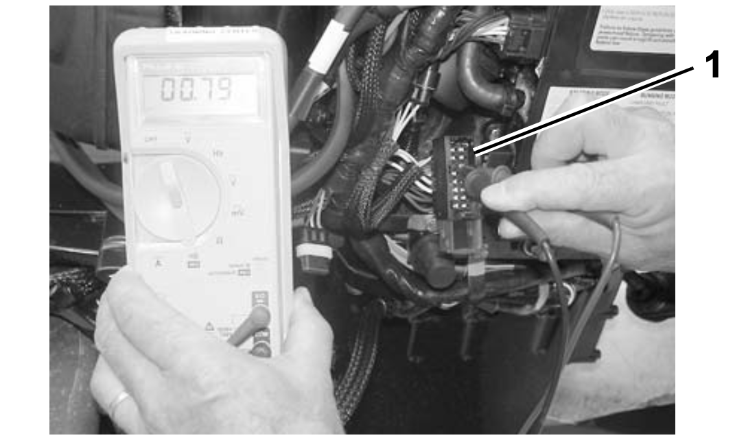
- Disconnect the EMM: Locate the EMM J2 connector and disconnect it from the EMM.
- Measure the stator winding resistance: The stator winding resistance specification is as follows:
- Yellow & Yellow/White: 0.670 ± 0.020 Ω @ 73°F (23°C)
- Brown & Brown/White: 0.670 ± 0.020 Ω @ 73°F (23°C)
- Orange & Orange/White: 0.670 ± 0.020 Ω @ 73°F (23°C)

1. EMM J2 Connector
- Connect the meter leads: Attach the meter leads to the following pins on the stator connector:
- Yellow/White and Yellow (pins 9 and 1)
- Brown/White and Brown (pins 10 and 2)
- Orange/White and Orange (pins 11 and 3)
- Check the resistance: Ensure that your meter is calibrated to read 1 ohm or less. A reading of less than 2 ohms is acceptable.
- Test for grounded windings: To check for a grounded winding, connect one meter lead to ground and alternately connect the other meter lead to each stator wire. The meter should not show continuity. If continuity is detected, it indicates a faulty stator that needs replacement.
Stator Voltage Output Test
Electric Start Models:
- Prepare the equipment: You will need a digital multimeter set to read 110 VAC output. Disconnect the crankshaft position sensor (CPS) to prevent accidental starting of the outboard.
- Disconnect components: Disconnect the CPS and the stator (6-pin) connector from the engine harness (6-pin) connector.
- Use the Stator Test Adaptor: Connect the Stator Test Adaptor tool, P/N 5005799, to the stator connector.
- Connect the meter leads: Attach the meter leads to the terminals of the adaptor tool.
- Start the outboard: With a fully charged battery, crank the outboard to a minimum of 300 RPM and observe the meter reading:
- 30 VAC at 300 RPM
- 40 VAC at 400 RPM
- 55 VAC above 500 RPM

1. Stator Test Adaptor
Rope Start Models
- Gather the necessary tools: You will need a Peak Reading Voltmeter, P/N 507972, set to the 50 VAC scale. Disconnect the CPS to prevent accidental starting of the outboard.
- Disconnect components: Disconnect the CPS, remove the spark plugs, and ensure the outboard is in Neutral. Disconnect the stator (6-pin) connector from the engine harness (6-pin) connector.
- Use the Stator Test Adaptor: Connect the Stator Test Adaptor tool, P/N 5005799, to the stator connector.
- Connect the meter leads: Attach the meter leads to the terminals of the adaptor tool.
- Rotate the flywheel: Use a long, steady pull on the starter rope to rotate the flywheel.
- Measure the stator output voltage: The stator output voltage should be approximately 30 VAC.

1. Stator Test Adaptor
Important Note: It's crucial to index all spark plugs before reassembling the engine. This ensures that each spark plug is returned to its original position.
By following these simple steps, you can effectively test the stator of your Evinrude E-TEC 40 thru 90 HP outboard engine. Regular stator testing is essential to identify any potential issues and ensure the optimal performance of your engine.
Remember, if you encounter any abnormalities during the testing process, such as readings outside the specified ranges or continuity between the stator windings and ground, it indicates a faulty stator that should be replaced.
Proper maintenance and regular testing of the stator can help you avoid costly repairs and keep your Evinrude E-TEC outboard engine running smoothly.


