Fuel Hose Routing Diagram Evinrude 40 50 60 65 75 90 HP
In this article, we delve into the fuel system hose routing illustration for 2009-2013 Evinrude E-TEC 40-90 HP model engines. Refer to the diagrams for accurate configuration and maximize the performance of your engine.
The fuel system of Evinrude E-TEC 40-90 horsepower engines is a crucial component responsible for delivering the correct amount of fuel to the engine for optimal performance. Understanding the hose routing is essential for proper maintenance and troubleshooting. In this article, we will provide an overview of the hose routing for both 2-cylinder and 3-cylinder models, along with a brief description of each numbered item in the diagram.
2-Cylinder Models
Let's start with the fuel system hose routing for 2-cylinder models. Refer to the provided diagram for a visual representation.

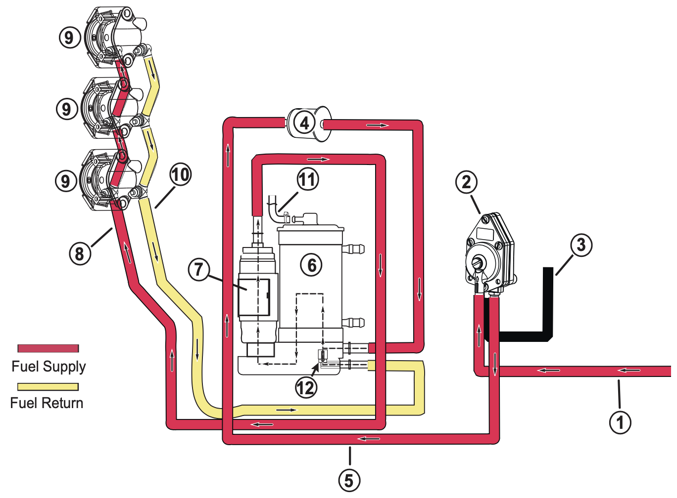
- Fuel Supply from Boat Fuel System: This is where the fuel enters the engine's fuel system from the boat's fuel tank.
- Fuel Lift Pump (2 to 8 psi): The fuel lift pump maintains the required pressure (2 to 8 psi) to supply fuel from the boat's fuel system to the engine.
- Pulse Hose from Cylinder/Crankcase: This hose carries pulses generated by the engine's cylinders or crankcase to operate the fuel pump.
- Fuel Filter: The fuel filter removes impurities and contaminants from the fuel, ensuring clean fuel reaches the engine.
- Fuel Supply to Vapor Separator: Fuel from the filter is directed to the vapor separator, a crucial component that separates air and vapor from the fuel.
- Vapor Separator: The vapor separator further filters the fuel, separating any remaining vapor or air bubbles, ensuring only liquid fuel is delivered to the engine.
- Electric Fuel Circulation Pump (20 to 30 psi): This pump increases the fuel pressure (20 to 30 psi) for efficient fuel injection into the engine's cylinders.
- Fuel Supply Manifold: The fuel supply manifold distributes the pressurized fuel evenly to each fuel injector.
- Fuel Injector(s): Fuel injectors deliver precisely measured amounts of pressurized fuel into each cylinder for combustion.
- Fuel Return Manifold: After the fuel is injected into the cylinders, any excess fuel is returned through the fuel return manifold.
- Vent Hose to Intake Manifold: The vent hose allows the engine to breathe by venting excess pressure from the intake manifold.
- Pressure Regulator (High Pressure): The pressure regulator controls the high-pressure fuel supply to ensure the fuel system operates within the specified pressure range.
3-Cylinder Models
Now, let's explore the hose routing for 3-cylinder models, which is similar to the 2-cylinder models. Again, refer to the diagram for a visual reference.

All the numbered items in the 3-cylinder model diagram correspond to the same components and functions as described for the 2-cylinder models.
Conclusion: Understanding the fuel system hose routing is vital for maintaining the optimal performance of your Evinrude E-TEC 40-90 horsepower engine. By following the proper routing and ensuring the components are functioning correctly, you can ensure a reliable fuel supply and efficient combustion. Regular inspection and maintenance of the fuel system will help prolong the engine's lifespan and ensure trouble-free operation on the water.


